Instrumentation and Process Control Teaching Equipment (Air Pressure and Flow) Didactic Equipment Modular Product System
Instrumentation and Process Control Teaching Equipment (Air Pressure and Flow) Didactic Equipment Modular Product System
Description
MR379E Instrumentation and Process Control Teaching Equipment (Air Pressure and Flow) Didactic Equipment Modular Product System
I. Product overview
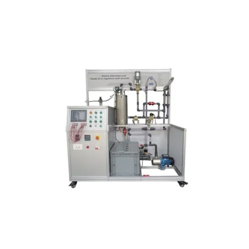
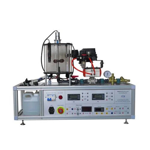
This training device is mainly composed of various types of industrial sensors, pneumatic controls, hydraulic controls, electrical switches, PLC programmable logic controllers, man-machine interfaces, etc., to cultivate students’ corresponding knowledge and skills.
(1) The training platform uses aluminum alloy substrates to build a training platform with a stable structure. Each actuator module is placed on the base plate, which is easy to use and not easy to damage.
(2) The training device is equipped with an electrical control cabinet, the power supply of the system is led out through a safety plug, and the wiring of the training device is connected through a terminal, which is safe and reliable.
(3) The organic integration of mechanical technology (including pneumatic technology), sensor technology, PLC control and communication network technology reflects the characteristics of the modern manufacturing production process. The overall structure adopts open and disassembly type, which can easily replace the modules. The content of the modules is determined according to the principles of productive functions and integrated learning functions, so that the required modules can be easily selected during teaching or competition.
(1) Input power: single-phase 120V±10% 50Hz
(2) Dimensions: 1250mm×600mm×1600mm
(3) Machine capacity: <1.5KVA
(4) Weight: <100kg
(5) Working conditions: ambient temperature -10℃~+40℃ relative humidity <85% (25℃)
The power input terminal is placed in the power distribution area on the training platform, led out through the plug, and the total power supply of the system is controlled by the leakage circuit breaker.
(1) The training platform is composed of an aluminum alloy frame, which can be placed on a level ground for experimentation. The structure is firm and beautiful.
(2) Accessories
USB cable
1-Touch screen 2-Power switch 3-Power indicator 4-Emergency stop switch 5-USB interface 6-Pump switch 7-Compressor switch 8-Analog fault 1 9-Analog fault 2
(1) Pneumatic control system
- Pressure reducing valve
Compressed air is supplied to all pneumatic components of the device through the pressure reducing valve. The outlet end of the pressure reducing valve is controlled by a valve, which is convenient for debugging. When the system is running, adjust the pressure value of the pressure reducing valve to 0.6MPa (pull up the pressure adjusting knob, turn the knob to adjust the pressure value to 0.6MPa, after the adjustment is completed, press the knob down to lock the knob and prevent it from rotating) .
1- Pressure adjustment knob 2- Air outlet 3- Air inlet 4- Air outlet switch 5- Pressure gauge
- Compressor
Compressed air input unit
1-switch 2-air outlet 3-pressure gauge 4-gas tank
1. Main interface
2. Pressure control experiment interface
3.Flow control experiment interface
4.Liquid level control experiment interface
IV. Can complete the training content
(1) Pressure control experiment
(2) Flow control experiment
(3) Liquid level control experiment
(4) Simulation failure experiment